Development of new chips for car manufacturers
Objective: Development of high-level microcontrollers for controlling car electronics in future cars of a new generation, including electric cars and hybrid cars.
Solution: Building an advanced HIL system on modular PXI and LabVIEW hardware.
“As a microelectronics manufacturer, we want to
be one step ahead of automakers, we solve
their problems before they face them. Therefore,
we came to HIL.
Instead of a full-size system like our
customers have, we put together a compact one - based on NI PXI with
FPGA models of all motors and devices. ”
Hideki Kagawa, Renesas Electronics
Accelerate Testing of Subaru's Hybrid Vehicle
Objective: To create an automatic verification system that meets quality requirements for the ECU of the first serial hybrid Subaru XV Crosstrek model, to implement complex tests that are difficult to recreate in real cars.
Solution: Execution of all possible patterns and reproduction of the most sophisticated cases to ensure a high level of security. Leverage the NI FlexRIO PXI Platform for the required control speed and critical execution speeds.

“Through FPGA-based simulations in
NI hardware and software, we achieved the speed
and accuracy of the models needed to verify
motor ECUs. We estimate that testing
took us 1/20 of the time of an equivalent test
on a dynamometer. ”
Tomohiro Morila, FUJI Heavy Industries / Subaru
HIL test of the inverter at the signal level
The software and electrical functionality of automotive inverters can be tested at the signal level using software and hardware simulation. Compared to traditional dynamometer testing, HIL allows testing earlier and cheaper, and also covers more complex and borderline cases. With rapidly evolving inverter technology and solutions, this flexibility and speed has become a necessity.
Primary requirements
• Execution of motor and environment models at frequencies greater than 100 kHz for adequate simulation accuracy.
• Ready-made models, tools, templates for a quick start of testing. Systems must be ready on a tight schedule and keep pace with changes in requirements and solutions from developers.
• Additional emulation of faults and errors: in hardware (open circuit, short circuit, etc.) and in software (network errors).
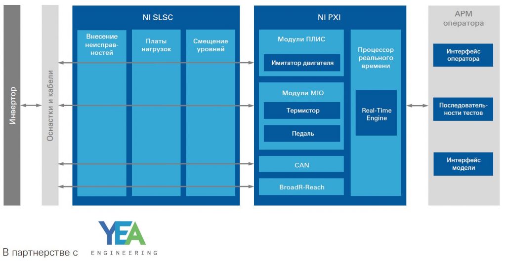
NI Solution
NI CompactRIO and
PXI hardware with powerful Xilinx FPGAs,
standard interfaces and a
set of universal
I / O lines .
Load electrical
models from swMATH SimPower
Systems, Powersim PSIM, NI
Multisim - directly into FPGA modules.
Hardware implementation of breaks,
short circuits, etc. in NI SLSC equipment,
simulation of software errors
directly in the FPGA.
HIL Simulation for Power Electronics BMS Testing
Testing battery management systems involves the complexities of high power and the inability to test multiple times with real batteries.
By emulating batteries and associated units, the system must check battery balancing, work out to counter failures, and ensure overall safety.
Primary requirements
• Emulation of battery cells in accordance with the models
• Providing simulation of faults and BMS signals
• Implementation of emulation of BMS sensors and communication with other units
NI Solution
Emulation of 12 battery cells with a Comemso BCS Precision Battery Simulator connected with a PXI CAN interface module. Simple expansion of the number of channels.
Integration of models for most types of batteries (NiMH, LiON, etc.), with different discharge characteristics.
Real-time test execution with VeriStand.
Expertise of the integrator in terms of additional protection, shunts, rigs and individual systems.
Use of ready-made solutions of partners for subsystems.
Test BMS firmware of JLR electric cars
Objective: To create a system for rapid prototyping and validation of firmware algorithms for battery management systems (Battery Management System, BMS). Provide safe testing of units with different battery technologies, failure scenarios and operating modes.
Solution: A system based on NI PXI and EtherCAT equipment, NI VeriStand software, LabVIEW and DIAdem. Bloomy BS 1200 Battery Simulators to simulate 24 hybrid and electric vehicle battery cells, each Bloomy running Single-Board RIO and LabVIEW FPGA.
“Now you can start
using a new firmware release within a week and be
sure of success. Previously, projects like this
took more than a month, with much less
certainty. ”
Miguel A. Gama, Jaguar Land Rover
HIL modeling of ADAS systems and unmanned vehicles
ADAS driver assistance systems and unmanned vehicles are increasingly shifting concerns about the safety of the driver, passengers and other road users to automation in the form of sensors, cameras, lidars, radars and, above all, computer algorithms in vehicle systems.
Algorithm testing and system testing is complicated by the required speed of time to market, maximum requirements for system reliability, a variety of sensors and their testing methods, constant updates and changes in requirements, technologies and expectations.
HIL software simulations and tests help meet this challenge.
YEA Engineering ADAS-HIL Platform
HIL systems for ADAS are designed to test both individual components of the system and their interaction within the framework of traffic scenarios. The ADAS-HIL platform in a typical configuration combines the following subtasks:
• Hardware and software simulation for ECU
• Simulation of obstacles for vehicle radars
• Simulation of obstacles for lidars
• Projection of video images onto the optical lens of the camera
• Simulation of GPS / GLONASS signals
HIL testing of radar sensors
Simulation of radar sensor signals uses re-emission of the received radio signal with a delay and frequency shift. Dynamic obstacle simulation requires a wide instantaneous bandwidth and exceptional performance, which is achieved through tight integration of FPGAs in NI radios.
The NI VRTS (Vehicle Radar Test System) kit provides object simulations for radars in the 76-81 GHz range. The minimum configuration for output control provides up to 4 simulated targets and is housed in an 8-slot PXI chassis. For more complex cases in research tasks, multi-module configurations are used based on one or more 17-word chassis.
Key parts of the VRTS:
• NI 5551 - VDG variable delay module with 4 GHz bandwidth
• NI 5840 - VST vector transceiver with FPGA
• NI mmRH-3608 - mmWave interchangeable radio heads
Test radar sensors in Audi
“The widest bandwidth and low latency of the NI VST have
allowed our radar sensors to be tested
like never before. We were able to
simulate a lot of scenarios in the early stages and solve problems
that we could not have noticed before. ”
Nils Koch, Audi AG
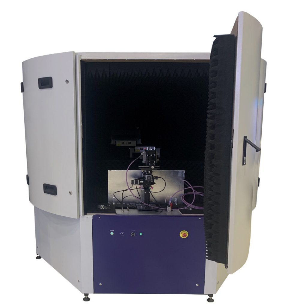
HIL testing system for radar sensors YEA Engineering
The system is part of the ADAS-HIL platform and serves to validate sensors, electronic control units and ADAS systems. Used by Tier 1 suppliers and automakers.
The system integrates an anechoic chamber, a set of control and measuring equipment, a positioning system and open-type software. This allows for common tests and provides the flexibility to create your own scenarios and measurements.